Knowledge Base
Engine Room Noise
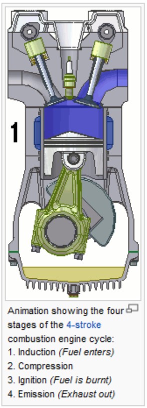
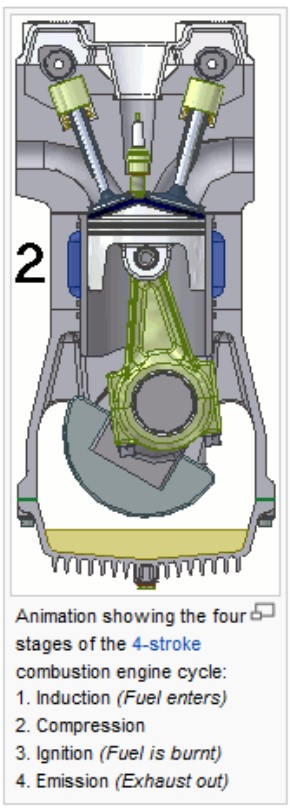
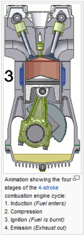
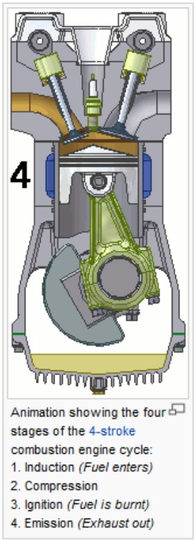
The above shown images indicates the four stage of a four-stroke engine. During operation an engine is causing:
- Air- borne noise due to radiated structure- borne noise
- Air- borne noise
- Structure- borne noise
- Vibrations
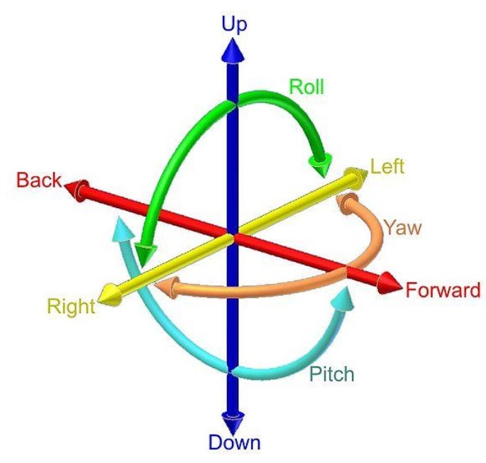
Vibrations : Image of the 6 degrees of freedom of a mass elastic system.
Air- borne noise due to radiated structure- borne noise:
During operation of a engine the engine block is radiating air- borne noise. This is a given fact in which engine producers spent more and more time to optimize the engine block and engine head to reduce radiated structure- borne noise.
Air- borne noise:
As an engine needs air to operate the air inlet is producing air- borne noise. Most of the engines have “standard” air inlet dampers (combined with filter). The combined damper and filter are very poor related to damping of air- borne noise.
Structure- borne noise:
During operation the engine is producing and transmitting structure- borne noise unto the ship foundation. In order to isolate the engine from the structure elastic mounting systems must be used.
Vibration:
During operation the engine is producing and transmitting vibrations (from 0 – 25 Hz). In order to isolate the engine from the structure elastic mounting systems must be used.
Absorption and Insulation:
As Engine Rooms are very noisy, in most cases above 100 dB (A), we have to think two ways knowing:
- How to reduce the noise levels inside the Engine Room.
- How to keep the noise inside the Engine Room.
Absorption:
In acoustics, absorption refers to the absorption of sound waves by a material. The absorption is the "missing piece", when comparing the total reflected and transmitted energy with the incident energy.
It is the property of a material that changes acoustic energy into usually heat energy. A material or surface that absorbs sound waves does not reflect them. Absorption of a given material is frequency-dependent and is affected by the size, shape, location, and mounting method used.
A good sound absorber is normally a porous material. Mineral wool, glass wool, and micro perforated plates work as sound absorbers.
Absorption is not a single mechanism of sound attenuation. Propagation through a heterogeneous system is affected by scattering as well.
Acoustical absorption is represented with the symbol A
Reverberation time
RT60 is the time required for reflections of a direct sound to decay by 60 dB below the level of the direct sound. Reverberation time is frequently stated as a single value however it can be measured as a wide band signal (20 hz to 20Khz) or more precisely in narrow bands (one octave, 1/3 octave, 1/6 octave, etc). Typically, the reverb time measured in narrow bands will differ depending on the frequency band being measured. It is usually helpful to know what range of frequencies are being described by a reverberation time measurement.
In the late 19th century, Wallace Clement Sabine started experiments at Harvard University to investigate the impact of absorption on the reverberation time. Using a portable wind chest and organ pipes as a sound source, a stopwatch and his ears, he measured the time from interruption of the source to inaudibility (roughly 60 dB). He found that the reverberation time is proportional to the dimensions of room and inversely proportional to the amount of absorption present.
Basic factors that affect a room's reverberation time include the size and shape of the enclosure as well as the materials used in the construction of the room. Every object placed within the enclosure can also affect this reverberation time, including people and their belongings.
Sabine equation
Sabine's reverberation equation was developed in the late 1890s in an empirical fashion. He established a relationship between the RT60 of a room, its volume, and its total absorption (in sabins). This is given by the equation:
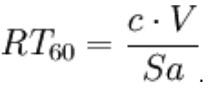
where c is a number that relates to the speed of sound in the room, V is the volume of the room in m³, S total surface area of room in m², a is the average absorption coefficient of room surfaces, and the product Sa is the total absorption in sabins.
The total absorption in sabins (and hence reverberation time) generally changes depending on frequency (which is defined by the acoustic properties of the space). The equation does not take into account room shape or losses from the sound traveling through the air (important in larger spaces). Most rooms absorb less sound energy in the lower frequency ranges resulting in longer reverb times at lower frequencies.
The reverberation time RT60 and the volume V of the room have great influence on the critical distance dc (conditional equation):
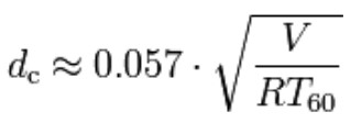
where critical distance dc is measured in meters, volume V is measured in m³, and reverberation time RT60 is measured in seconds.
Absorption
The absorption coefficient of a material is a number between 0 and 1 which indicates the proportion of sound which is absorbed by the surface compared to the proportion which is reflected back into the room. A large, fully open window would offer no reflection as any sound reaching it would pass straight out and no sound would be reflected. This would have an absorption coefficient of 1. Conversely, a thick, smooth painted concrete ceiling would be the acoustic equivalent of a mirror, and would have an absorption coefficient very close to 0.
Measurement of reverberation time
Historically reverberation time could only be measured using a level recorder (a plotting device which graphs the noise level against time on a ribbon of moving paper). A loud noise is produced, and as the sound dies away the trace on the level recorder will show a distinct slope. Analysis of this slope reveals the measured reverberation time. Some modern digital sound level meters can carry out this analysis automatically.
Currently several methods exist for measuring reverb time. An impulse can be measured by creating a sufficiently loud noise (which must have a defined cut off point). Impulse noise sources such as a blank pistol shot or balloon burst may be used to measure the impulse response of a room.
Alternatively, a random noise signal such as pink noise or white noise may be generated through a loudspeaker, and then turned off. This is known as the interrupted method, and the measured result is known as the interrupted response.
Reverberation time is usually stated as a decay time and is measured in seconds. There may or may not be any statement of the frequency band used in the measurement. Decay time is the time it takes the signal to diminish 60 dB below the original sound.
Soundproofing / Sound Insulation:
Soundproofing is any means of reducing the sound pressure with respect to a specified sound source and receptor (noise control). There are several basic approaches to reducing sound: increasing the distance between source and receiver, using noise barriers to block or absorb the energy of the sound waves, using damping structures such as sound baffles, or using active antinoise sound generators.
Soundproofing affects sound in two different ways: noise reduction and noise absorption. Noise reduction simply blocks the passage of sound waves through the use of distance and intervening objects in the sound path. Noise absorption operates by transforming the sound wave. Noise absorption involves suppressing echoes, reverberation, resonance and reflection. The damping characteristics of the materials it is made out of are important in noise absorption. The wetness or moisture level in a medium can also reflect sound waves, significantly reducing and distorting the sound traveling through it, making moisture an important factor in soundproofing.
Materials used for Sound Absorption:
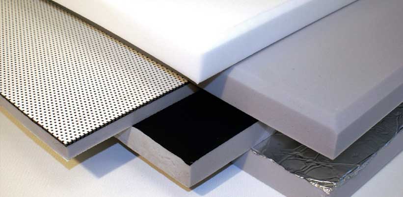
SLP – FLAME
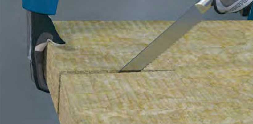
SLP – STONEWOOL
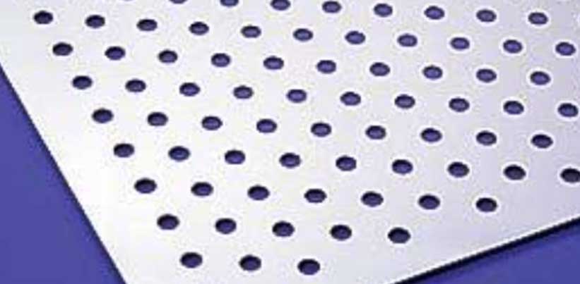
SLP – PERF. PLATE
For additional information on Silent Line Products (SLP) materials check www.silentlinegroup.com
Materials used for Sound Proofing / Insulation:
SLP – STONEWOOL

SLP – MASS
SLP – SONIC
For additional information on Silent Line Products (SLP) materials check www.silentlinegroup.com
Additional Silent Line Products Materials:
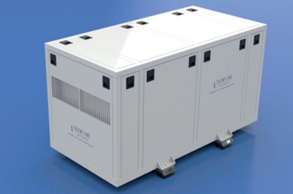
SLP – CUSTOM BUILD SOUND SHIELDS
SLP – AIR INLET DAMPERS (CUSTOM BUILD)
Structure- borne noise and Vibration:
All rotating / reciproke machinery inside an Engine Room is producing vibrations / structure- borne noise. The difference between vibration and structure- borne noise is that vibrations is between approx. 0 – 25 Hz while structure- borne noise starts at approx. 25 Hz up to 20.000 Hz
At all cases it is important to isolate the sound source (rotating / reciproke machinery) from the ship structure using elastic mounting systems.
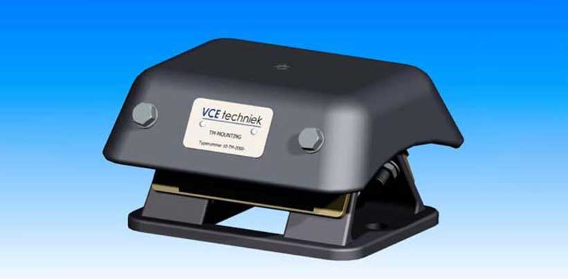
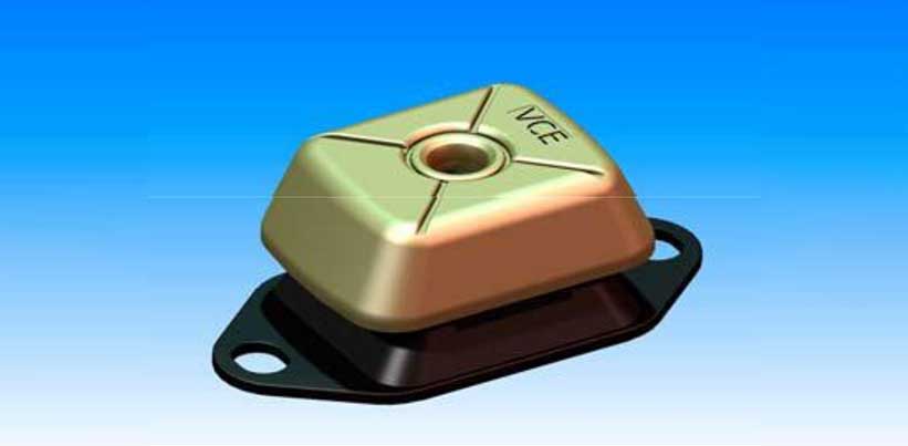
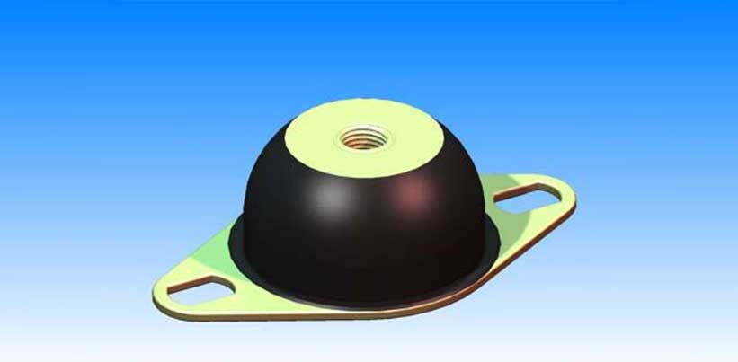
The correct type of mounting system must be calculated by means of a computer simulation model (6-Degrees of Freedom Calculation). By means of data abstracted from the type of machinery and typical data of the mounting the six natural frequencies of the mass-elastic system are calculated.
Please note that all connections to the sound source (machinery) must be flexible as well. This means flexible hoses, compensators etc.
Important note: Both air- borne noise and structure- borne noise (vibrations) must be BALANCED in order to achieve acceptable noise levels onboard. A good isolated Engine Room with a fixed mounted main engine or gearbox does not make sense and is a waste of time and money.
Thrust bearing & flexible coupling:
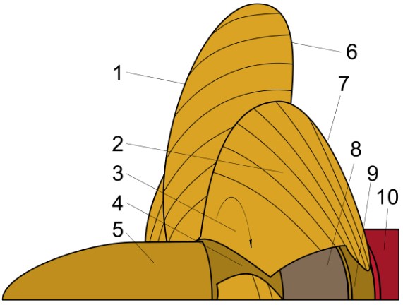
A propeller is the most common propulsor on ships, imparting momentum to a fluid which causes a force to act on the ship.
The ideal efficiency of any size propeller (free-tip) is that of an actuator disc in an ideal fluid. An actual marine propeller is made up of sections of helicoidal surfaces which act together 'screwing' through the water (hence the common reference to marine propellers as "screws"). Three, four, or five blades are most common in marine propellers, although designs which are intended to operate at reduced noise will have more blades. The blades are attached to a boss (hub), which should be as small as the needs of strength allow - with fixed pitch propellers the blades and boss are usually a single casting.
An alternative design is the controllable pitch propeller (CPP, or CRP for controllable-reversible pitch), where the blades are rotated normal to the drive shaft by additional machinery - usually hydraulics - at the hub and control linkages running down the shaft. This allows the drive machinery to operate at a constant speed while the propeller loading is changed to match operating conditions. It also eliminates the need for a reversing gear and allows for more rapid change to thrust, as the revolutions are constant. This type of propeller is most common on ships such as tugs[citation needed] where there can be enormous differences in propeller loading when towing compared to running free, a change which could cause conventional propellers to lock up as insufficient torque is generated. The downsides of a CPP/CRP include: the large hub which decreases the torque required to cause cavitation, the mechanical complexity which limits transmission power and the extra blade shaping requirements forced upon the propeller designer
For smaller motors there are self-pitching propellers. The blades freely move through an entire circle on an axis at right angles to the shaft. This allows hydrodynamic and centrifugal forces to 'set' the angle the blades reach and so the pitch of the propeller.
A propeller that turns clockwise to produce forward thrust, when viewed from aft, is called right-handed. One that turns anticlockwise is said to be left-handed. Larger vessels often have twin screws to reduce heeling torque, counter-rotating propellers, the starboard screw is usually right-handed and the port left-handed, this is called outward turning. The opposite case is called inward turning. Another possibility is contra-rotating propellers, where two propellers rotate in opposing directions on a single shaft, or on separate shafts on nearly the same axis. One example of the latter is the CRP Azipod by the ABB Group. Contra-rotating propellers offer increased efficiency by capturing the energy lost in the tangential velocities imparted to the fluid by the forward propeller (known as "propeller swirl"). The flow field behind the aft propeller of a contra-rotating set has very little "swirl", and this reduction in energy loss is seen as an increased efficiency of the aft propeller.
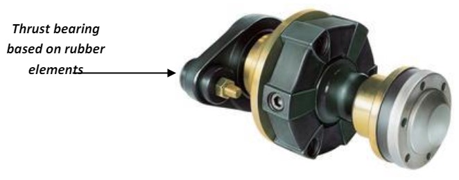
The above shown image indicates a combination of a thrust bearing (which absorbs the thrust emitted by the propulsion propeller) and a flexible coupling in order to allow a soft mounting system underneath the main engine / gearbox combination. Various options are available concerning thrust bearings and flexible couplings.
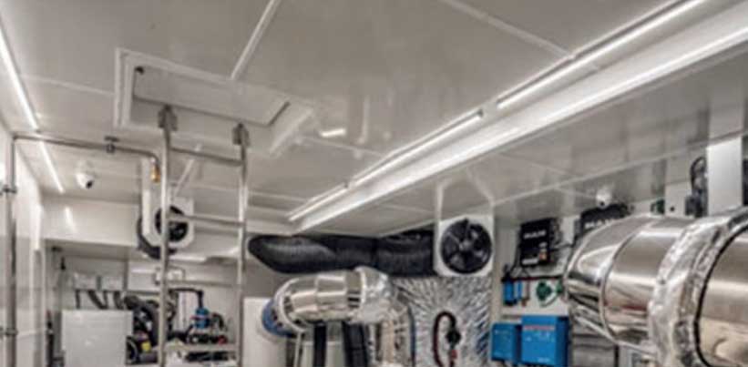
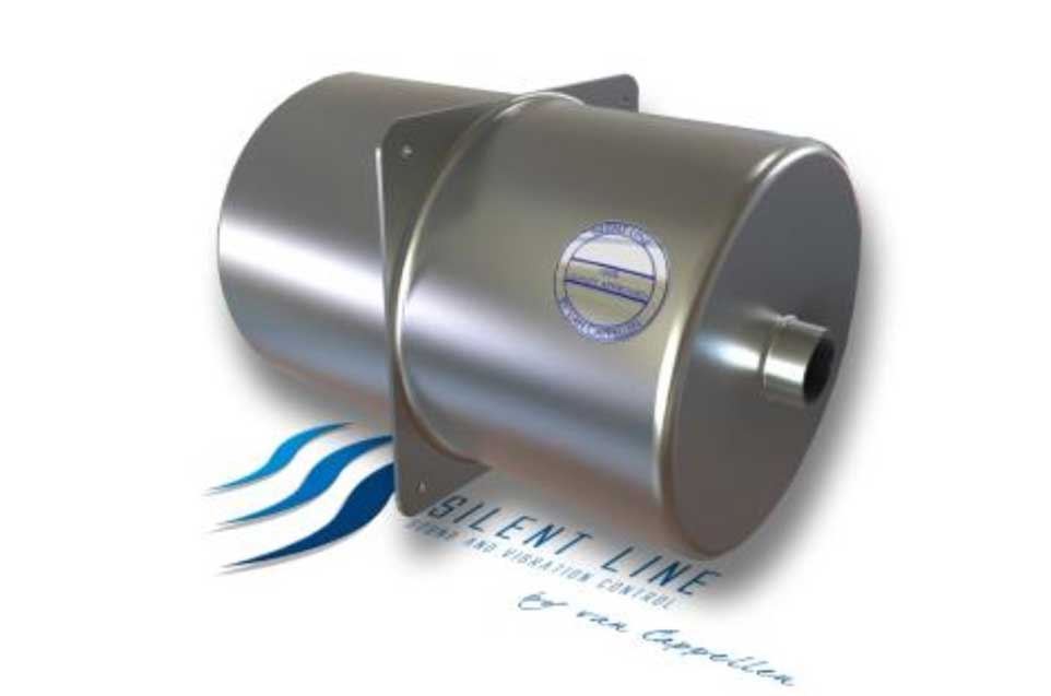
Engine Room ventilation system:
If equipped with internal combustion or turbine engines, engine rooms employ some means of providing air for the operation of the engines and associated ventilation. If individuals are normally present in these rooms, additional ventilation should be available to keep engine room temperatures to acceptable limits. If personnel are not normally in the engine space, as in many pleasure boats, the ventilation need only be sufficient to supply the engines with intake air. This would require an unrestricted hull opening of the same size as the intake area of the engine itself assuming the hull opening is in the engine room itself. Commonly screens are placed over such openings and if this is done, airflow is reduced by approximately 50% so the opening area is increased appropriately. The requirement for general ventilation and the requirement for sufficient combustion air are quite different. A typical arrangement might be to make the opening large enough to provide intake air plus 1000 Cubic Feet per Minute (CFM) for additional ventilation. The engines will pull sufficient air into the engine room for their use. However, to achieve the additional airflow desired, intake/exhaust blowers will probably be required because the engines will only generate airflow sufficient for their demand at the time
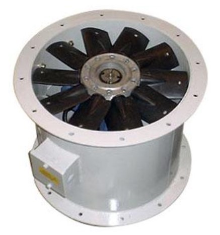
Special dampers (custom build or standard) can be supplied by Silent Line Products in order to reduce noise emitted by fans.
The above shown Engine Room fan has 10 blades and runs at (maximum speed) 3000 rpm. This means 3000 / 60 / 10 blades = 500 Hz (propeller blade frequency). Pending on speed, volume, class of fan etc. noise levels between 90 – 95 dB (A) can be expected (measured at 1 mtr. from the fan at 45 degrees angle).
Without proper anti – noise measures (damper or coulisse or labyrinth) high levels of noise will occur at other deck area(s) in the close surroundings of the Engine Room intake(s).